The problem
D03 showed that about 35 kW of heat flow into the wall of WD-01, while its methane can absorb only about 12 kW. Before designing cooling channels, we measured what each possible fix is worth.
The levers
A shorter chamber (less wall), oxygen as a second coolant, a wall that may run hotter, a fuel-rich layer of gas along the wall set by the injector, and a wall of high-temperature metal that glows and radiates its heat into space. For the wall layer, 10 % of the flow burns fuel-rich next to the wall while the core burns slightly leaner, so the overall mixture stays the same.
What we found
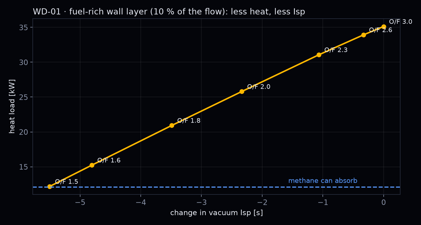
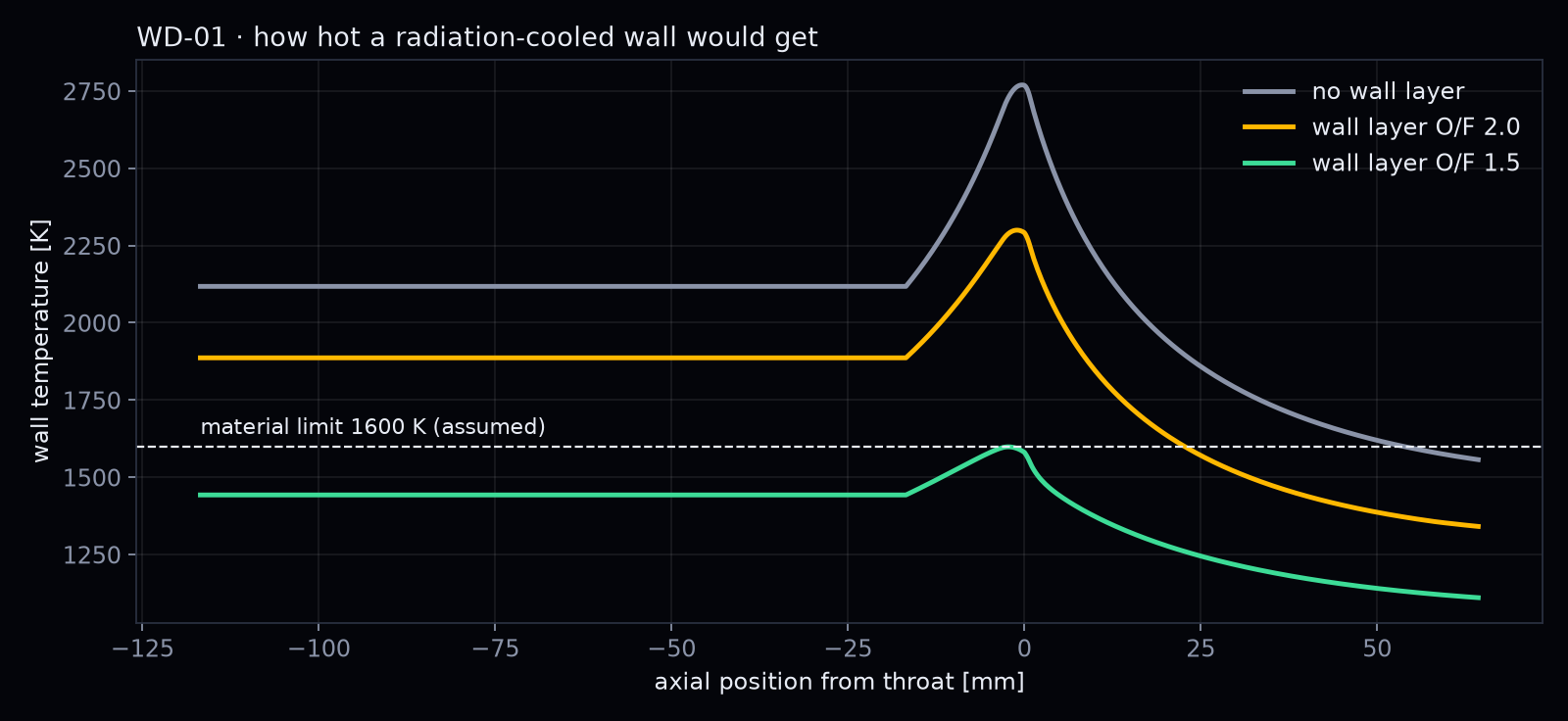
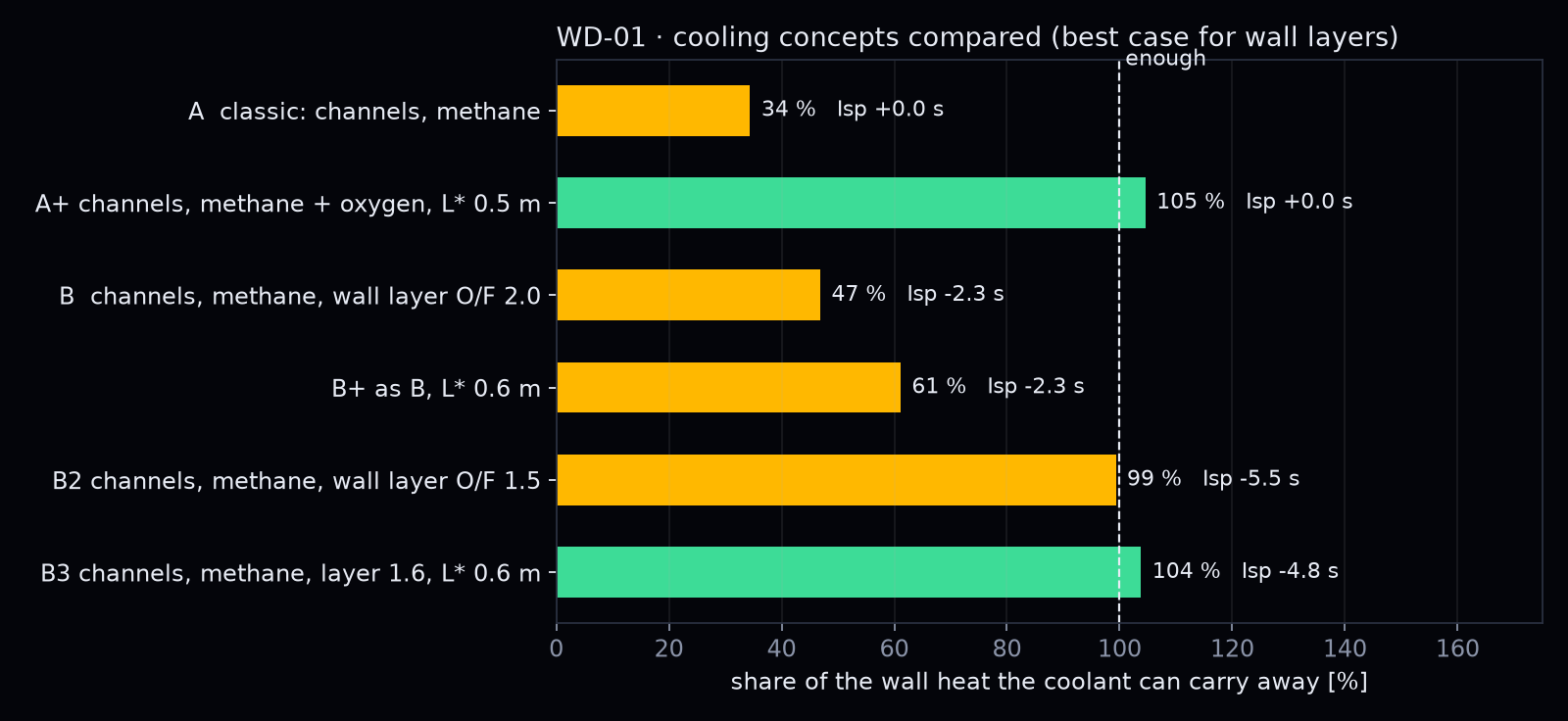
A shorter chamber or a hotter wall each remove only a few kilowatts. A much shorter chamber plus oxygen cooling closes the gap, but needs two cooling circuits. The fuel-rich wall layer is the strongest lever: in the best case it cuts the heat load from 35 to 12 kW for 5.5 s of Isp, and methane alone becomes enough. A glowing wall is useless on its own (the throat would reach about 2,770 K) but works together with the layer, right at the assumed material limit, without a single cooling channel.
What we take from it
None of this is new. Rocket engineering textbooks have said it for decades: small engines are hard to cool regeneratively, film and barrier cooling are the strongest levers, and small radiation-cooled thrusters rely on them. We recalculated it for our engine and published the notebooks so that every later design has an honest baseline.
What the textbooks cannot tell us is the open question behind every promising concept: how long does the cool layer stay at the wall? That depends on the shape of the injector and the chamber, and no one-dimensional correlation can answer it. This is where we will aim our CFD and, from week 2, the AI. If an AI-designed engine keeps that layer in place better than a classic design, that would be a real result. Until then it is a goal, not a finding.