Warp Dynamics / Engineer's log / Run 03
Engineer's log, stardate 2026.10.22Run 03

Can a 100 N engine cool itself?

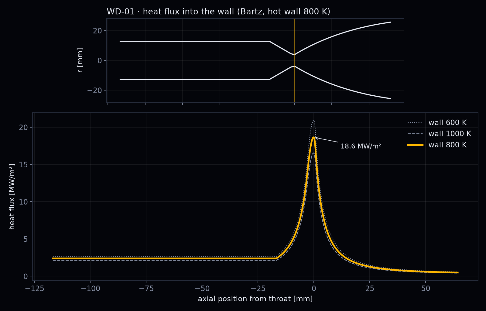
About 35 kW of heat flows into the wall of WD-01, peaking at 19 MW/m² at the throat. Methane alone can carry away only about a third of it.

Peak heat flux
18.6 MW/m²
Total heat load
35 kW
Methane can absorb
12 kW
Methane + oxygen
27 kW
Heat flux along the WD-01 wall, flat in the chamber and peaking at 18.6 MW per square metre at the throat
Heat flux along the wall for hot-wall temperatures of 600, 800 and 1,000 K.

The question

The gas inside WD-01 is at about 3,250 K. Copper alloys lose their strength far below that. The usual answer is regenerative cooling: the propellant flows through channels in the wall before it is burned. Before we design those channels, we need the heat load.

How we computed it

The full inner wall, from injector to exit, with the gas state from D01. The heat-transfer coefficient follows the Bartz correlation, the standard first estimate for rocket nozzles, using viscosity, heat capacity and Prandtl number from NASA CEA. We assumed a hot-wall temperature of 800 K and also tried 600 and 1,000 K.

What we found

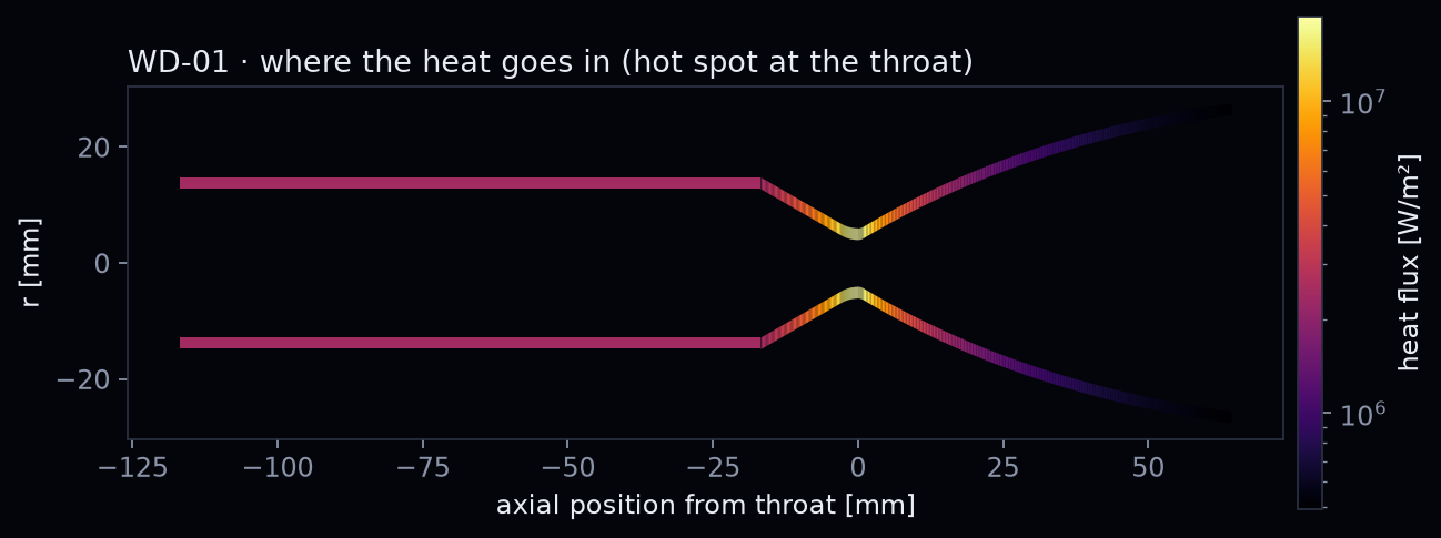
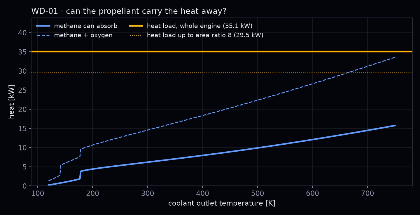
The heat flux peaks at 18.6 MW/m² right at the throat: almost 2 kW through every square centimetre, the power of a kitchen hot plate. In total 35 kW flow into the wall, and the long cylindrical chamber takes the largest share, 19 kW. Heated to 600 K, the 7 g/s of methane can absorb only 12 kW, about a third. Methane and oxygen together reach 76 %.

What it means

On paper, WD-01 cannot cool itself with methane alone. Small engines have this built in: the wall shrinks more slowly than the propellant flow that has to cool it. Shortening the chamber to L* = 0.5 m and cooling with both propellants would just cover the load. Film cooling and a radiation-cooled nozzle end are the other levers. Run D04 decides which ones WD-01 needs.
From the calculation

day03_wd01_heat_flux.ipynbexcerpt, simplified
hg = 0.026 / Dt0.2 · (μ0.2 cp / Pr0.6)0 · (pc / c*)0.8 · (Dt / R)0.1 · (At / A)0.9 · σ  q = hg (Taw − Tw)
# Bartz (1957), transport properties from NASA CEA
h_t = 0.026/Dt**0.2 * MU**0.2*CP/PR**0.6 * (PC/CSTAR)**0.8 * (Dt/R_CURV)**0.1
sigma = 1/((0.5*Tw/T0*T0/T + 0.5)**0.68 * (T0/T)**0.12)
h = h_t*(At/A)**0.9*sigma
q = h*(T + PR**(1/3)*(T0 - T) - Tw)      # adiabatic wall minus hot wall
Peak heat flux 18.6 MW/m² at the throat (h_g = 7682 W/m² K)
Total heat load 35.1 kW  (chamber + converging 25.0 kW, bell 10.1 kW)
Heat the propellant can absorb up to 600 K outlet:
  methane only    12.1 kW   ( 34 % of the load)
  both            26.7 kW   ( 76 %)
WD-01 wall coloured by heat flux, bright hot spot at the throat
Where the heat goes in: the throat is the hot spot, the long chamber takes the most in total.
Heat the propellants can absorb versus coolant outlet temperature, below the 35 kW heat load
Heat load against what methane, and methane plus oxygen, can absorb.

Simulation, not test results · Published 2026-10-22